Alternative Wireless remote design
This is an alternative wireless remote design for EBikes and/or GPS bike computers like the Garmin Edge.
If you do not want to build your own, you can purchase on the market EBike remote controls. ie: the Garmin EBike Remote for about 80€.
However, our wireless remote control is considerably less expensive (costs 20€ in materials) and offers several additional features for EBike control.
Features:
- turn on/off the motor
- increase/decrease assist level
- turn on/off walk assist
- turn on/off lights
- show battery level
- send the brake signal
- RGB LED to provide visual feedback
- battery should last for more than 2 years
- Garmin Edge page change
Re-design Considerations
Although the original 3D printed case design has a number of very good features, (ie: it is very compact on the handlebar!), I wanted to redesign the enclosure to add a number of features that I find useful.
Note, the design choices made were for my use of the remote with my e-bike and you were may find the original design more to your liking.
Please choose the design that works for you.
The thoughts that went into the re-design are as follows:
In the original design I find the keypad to be quite high and thus hard to reach with my thumb. The keypad ended up high due to design choice to stack all the components vertically. This re-design allows for a very low keypad in two ways, first by extending the remote along the bar length , and second by using tie wraps to clamp the remote to the handlebar which reduces the need for some plastic height needed to screw in the clamping ring in the older design. (see next bullet below)
Removed the clamping U-bolt and associated screws and replaced with a tie-wrap clamping method for the handlebar. The reason for this is because I have found that screws used for this purpose in PLA plastic may loosen with time, leading to potential slippage on the handlebar. I have had good success with tie wraps for bicycle accessories as they can be very neat and tidy while providing a strong clamp to the handlebar.
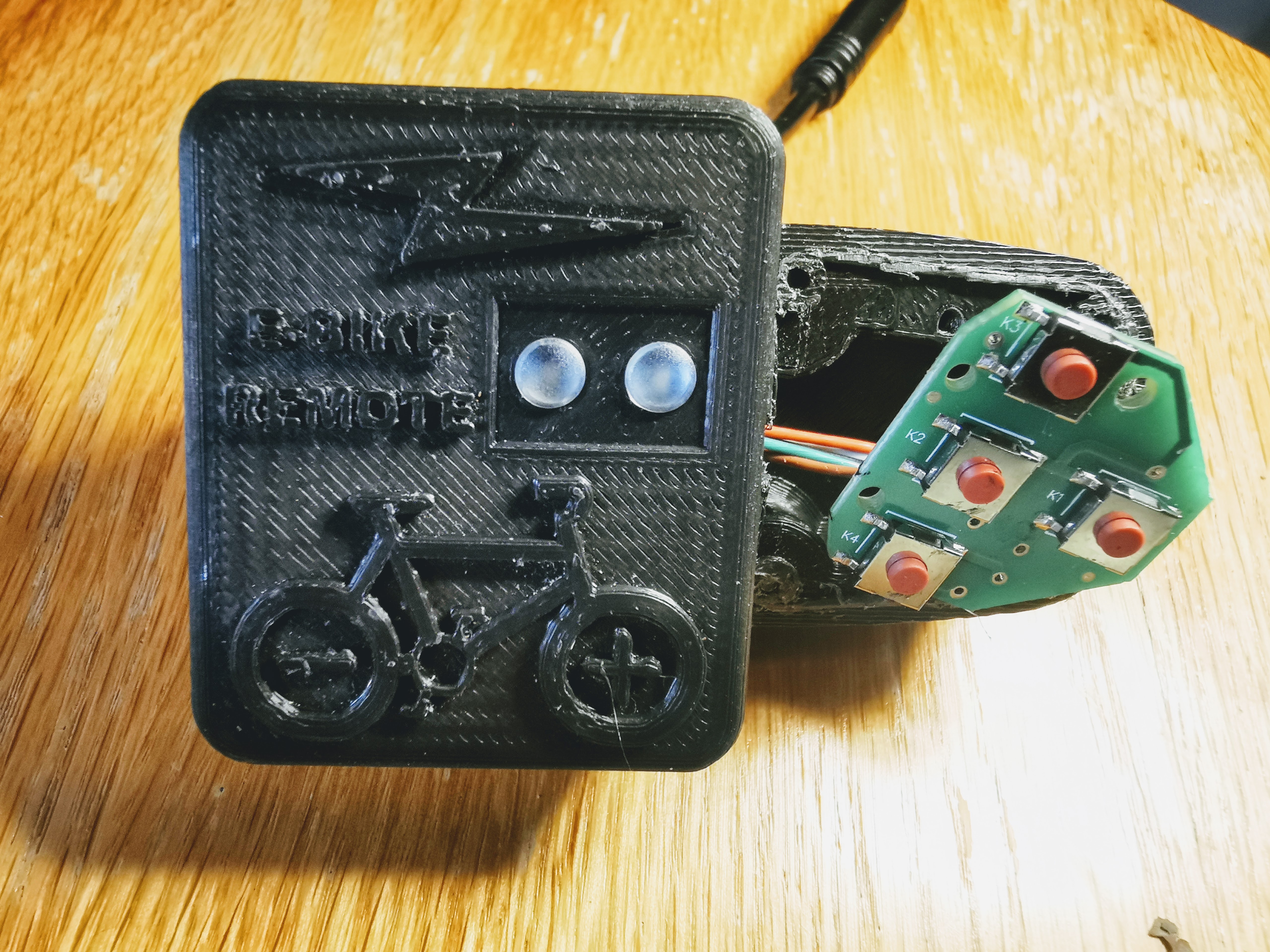
Eliminated the need the cut the end off the nrf52840 to reduce it's length. The re-deign allows for the nrf52840 to be dropped into the case without modification
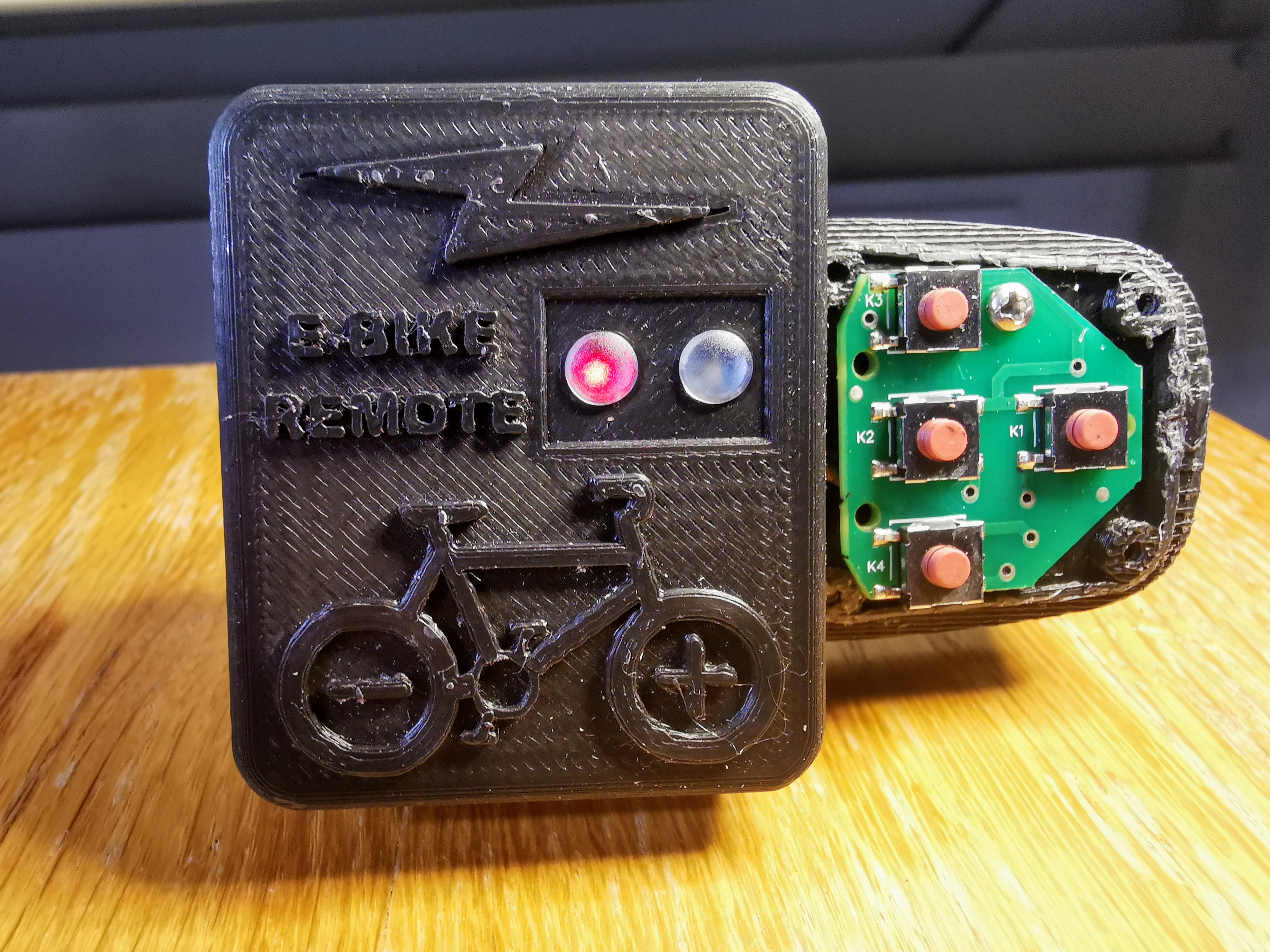
Added LED light pipes to the case to transmit lights from the leds. This avoids the use of clear silicone or epoxy and allows for brighter displays. I also added support in the case for both board leds. Note that at present we do not use the green led for any display information. However, this design will allow for that possibility in the future. (ie: display of motor error codes)
Added design options for both the 25.4 mm and 31.8 mm bicycle handlebar standards. Many new mountain bike frames are moving to a 31.8mm diameter.
The design can also be mirrored to satisfy the needs of left handed cyclists.
Added a button recess in the 3d design to prevent the button on the board from being accidentally pressed when installed in the remote case.
Although the battery life with a cr2032 coin cell with the original design is well over 1 year, the re-design allows for the addition of a MUCH larger battery, namely the CR123A. This lithium battery has a capacity of 1500 mah, vs the 230 mah of a typical cr2032 coin cell. This is a improvement in battery life of over 6.5 times! This effectively eliminates any concerns that a user may have around battery life. The battery is also positioned to allow for easy replacement.
Reused the hardware from the original remote control. The same screws are used to attach the remote to the re-designed enclosure.
Eliminated the use of screws anywhere else in the design. The enclosure uses a snap on lid.
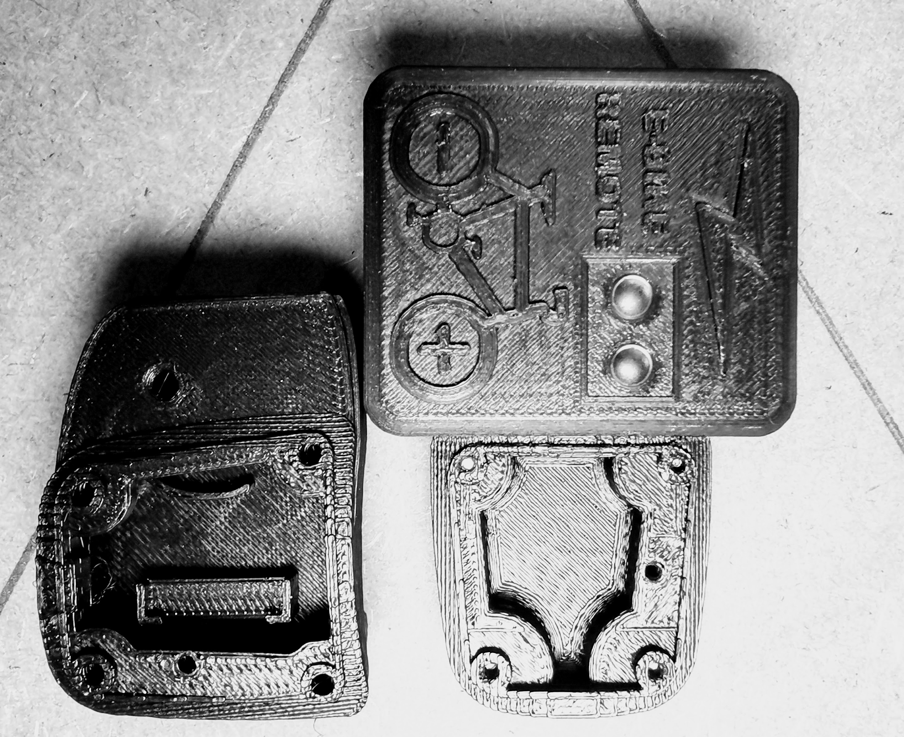
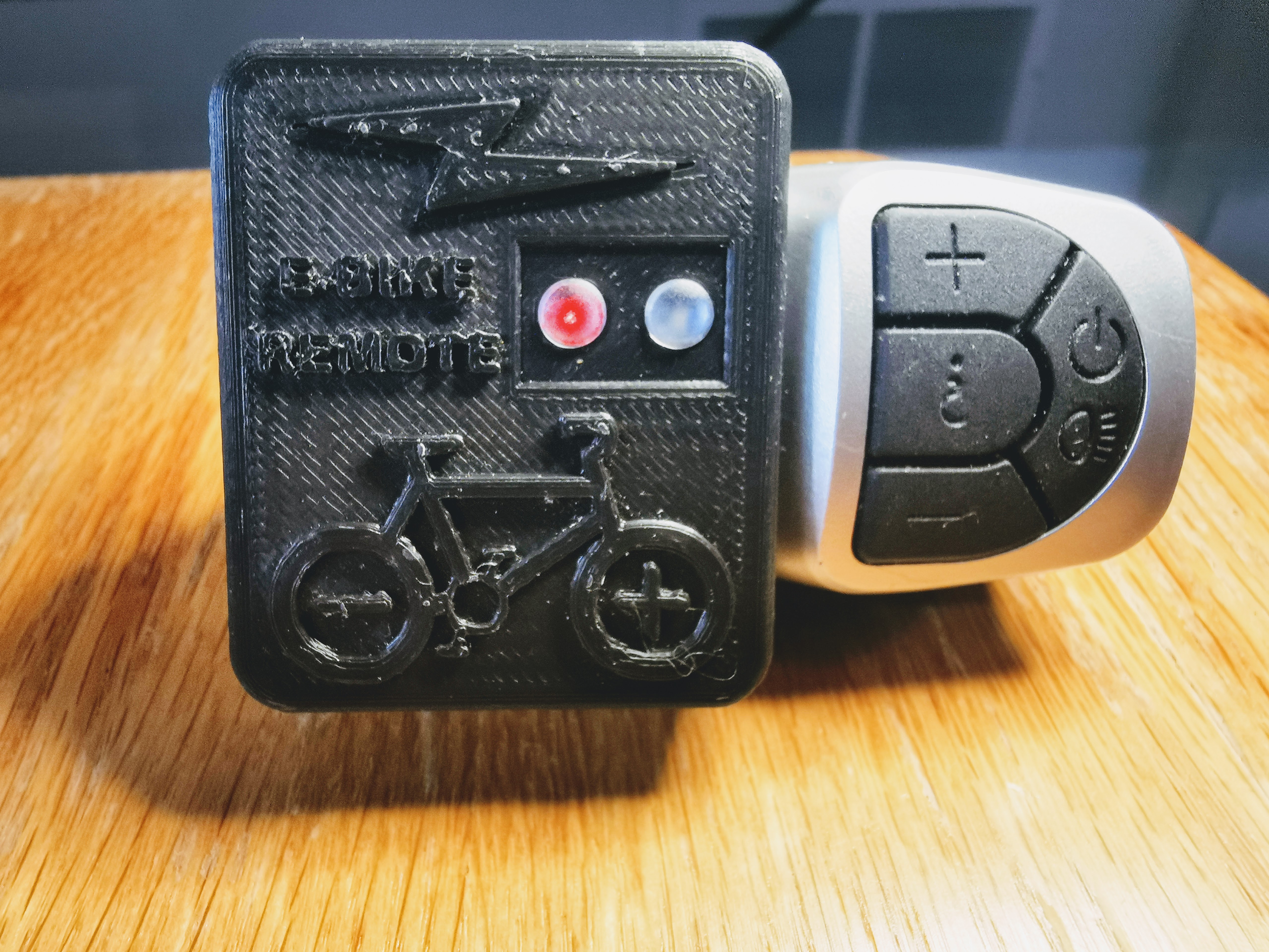
The main disadvantage of this design approach is that the design is MUCH bigger. ie: See the new 3d design beside the original design:
I designed the remote using Fusion 360. The design files are located in the 3d_design_files folder. I have also included .step files to allow importing into other 3d design packages like Freecad. The resulting design looks like [this](https://tinyurl.com/7b3r8s2r)
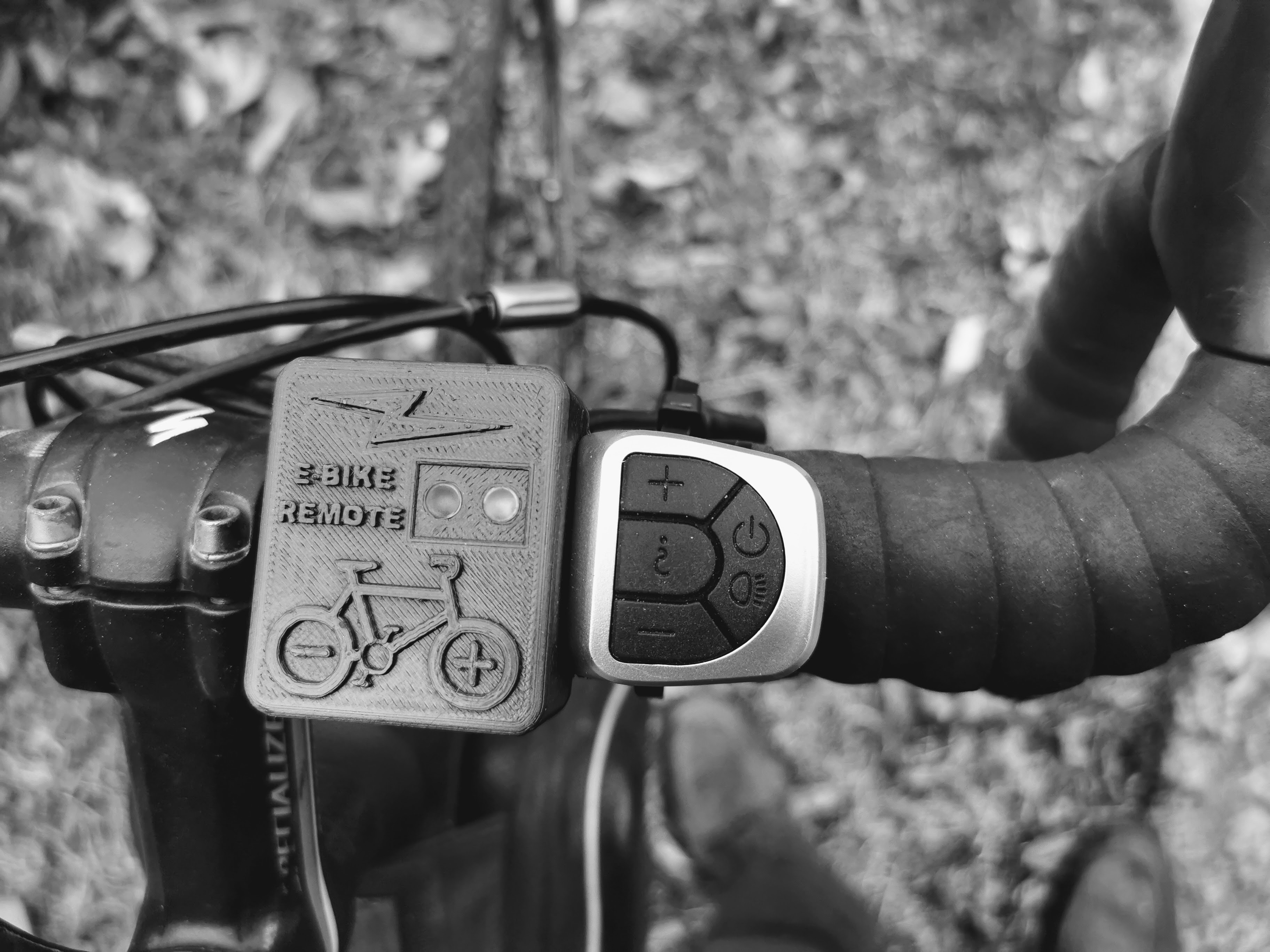
Installed on the handle bar:
How to build the wireless remote
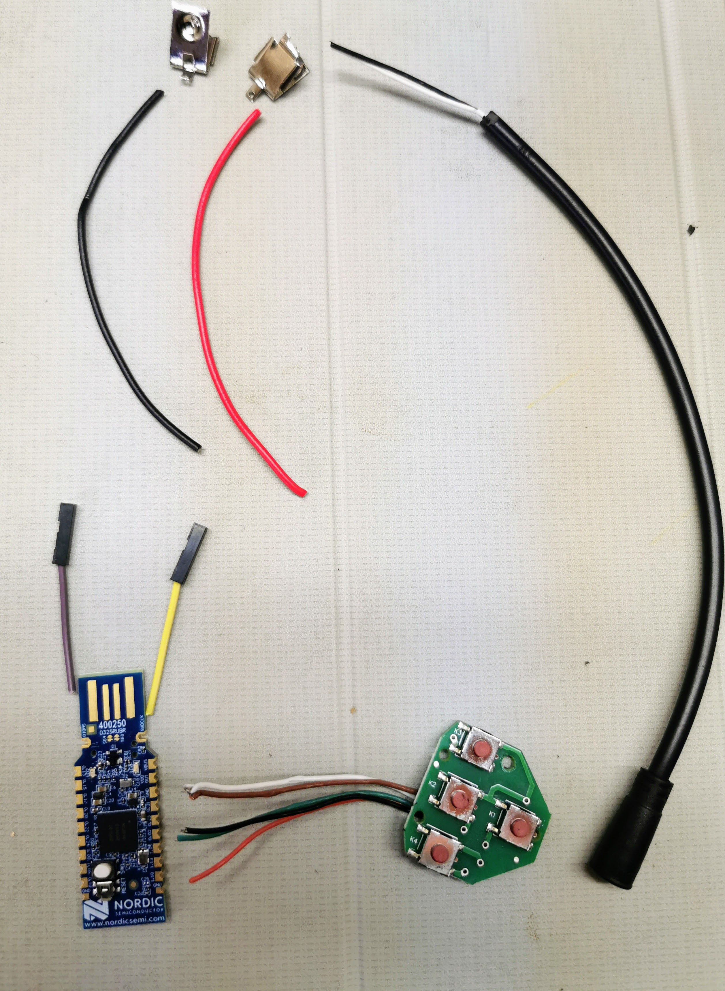
You will need the following components:
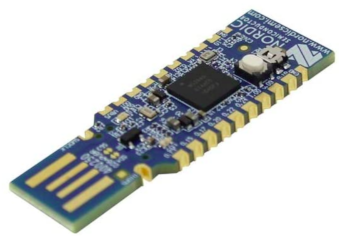
nRF52840 Nordic USB Dongle
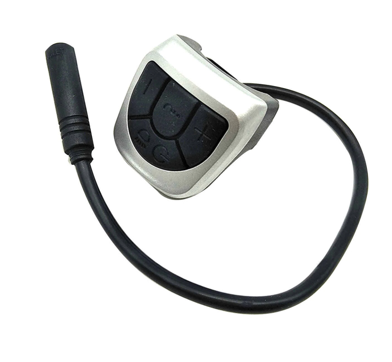
VLCD5 display keypad or 860C display keypad: costs 10€, this is the keypad from the TSDZ2 original display. Can be bought in many online shops like EBay.
![] (VLCD5_keypad.png)CR123 3V battery: costs 1€, can be bought in any local shop or on EBay or other online shops.
2.54mm light pipes: These can be purchased on Aliexpress or ebay. ie AliExpress
Alternatively, you can use a drop of clear silicone, although the light transmission will not be as good.
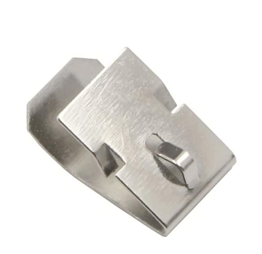
Battery Clips: These can be purchased on Aliexpress or ebay. ie AliExpress
3D printed enclosure: NOTE that if you do not have a 3D printer, you can improvise by simple use some black tape to protect the board, wires and the battery. If you 3D print this enclosure, it should costs about 1€.
Optional components:
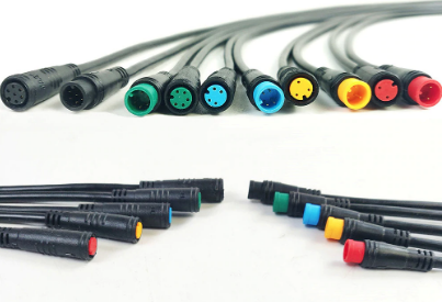
- Cable with 2 pins and water prof connector: costs 4.5€, with a good connector used on EBikes, to connect to the brake sensors. Can be bought in many online shops like EBay - search for "julet mini connector" or "higo connector" and choose the 2 pin male and female, red color.
Step by step instructions
1 - Flash bootloader on the nrf52840 board - see the page: How to Flash the Wireless Bootloader on a Nordic Dongle
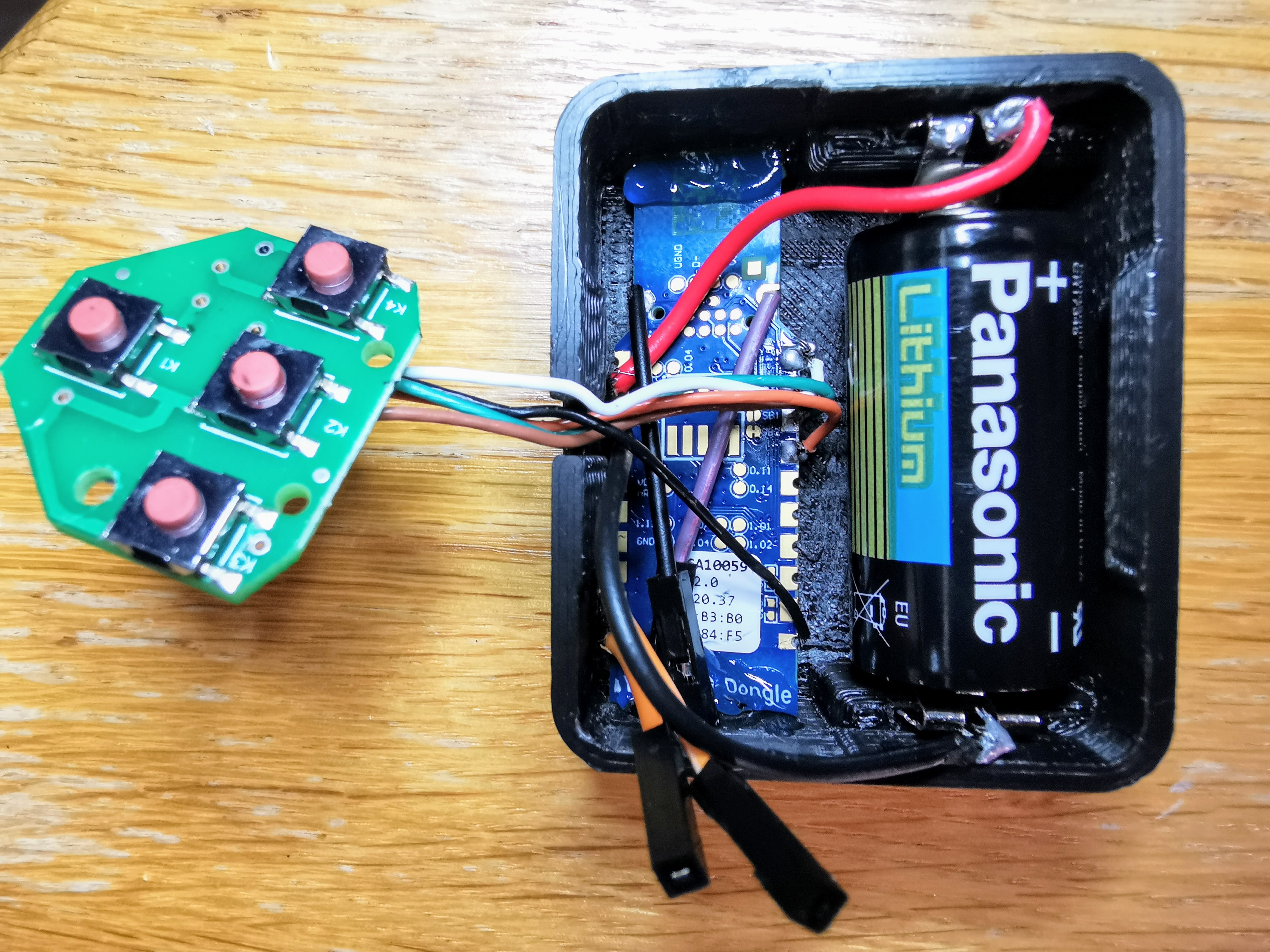
2 - Build your board - solder all the wires following this schematic. (use cr123 battery where it shows cr2032 battery)
Do not solder any wires to the battery, it would be dangerous. Simple solder to the battery clips and insert them into the case
Schematic:
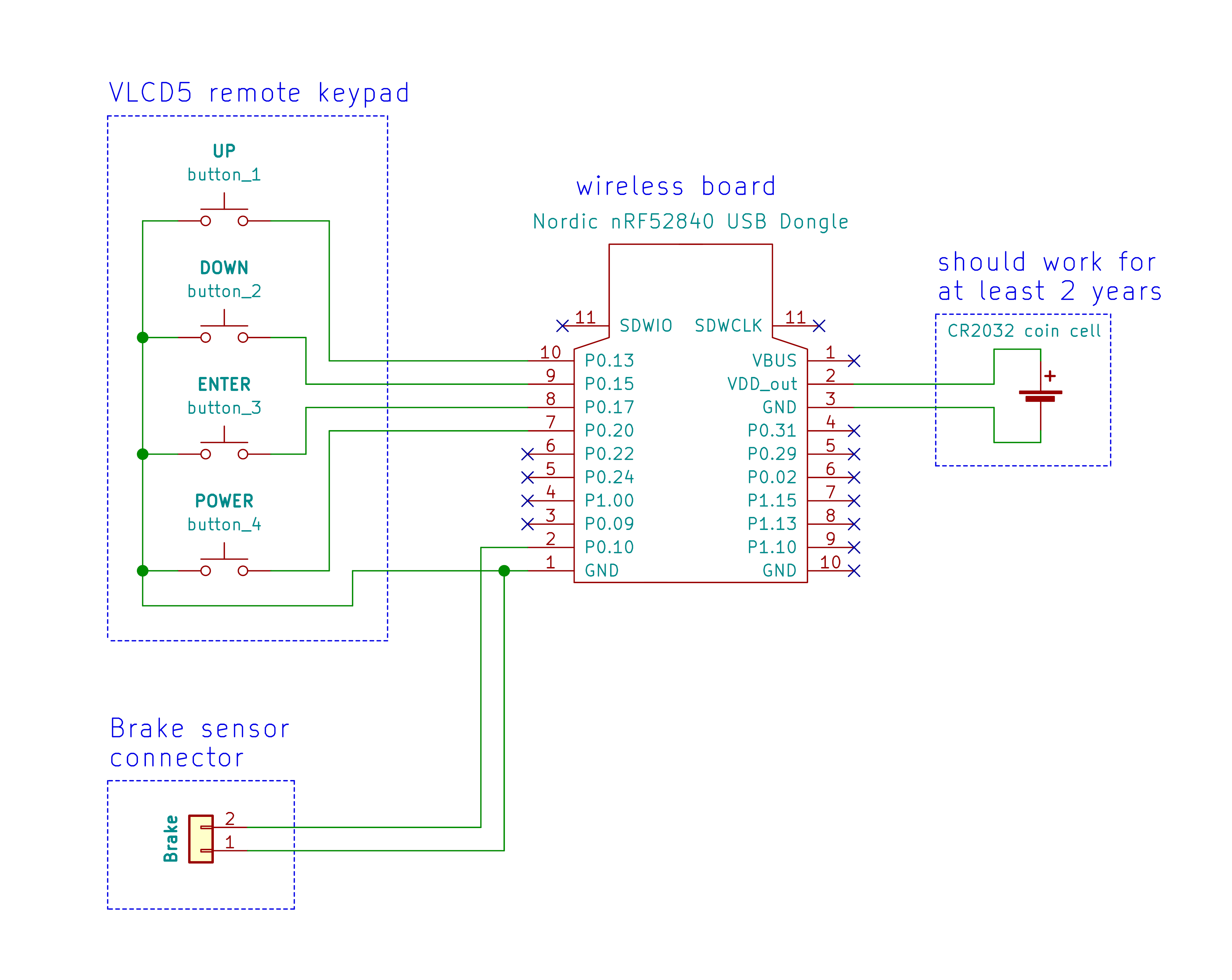
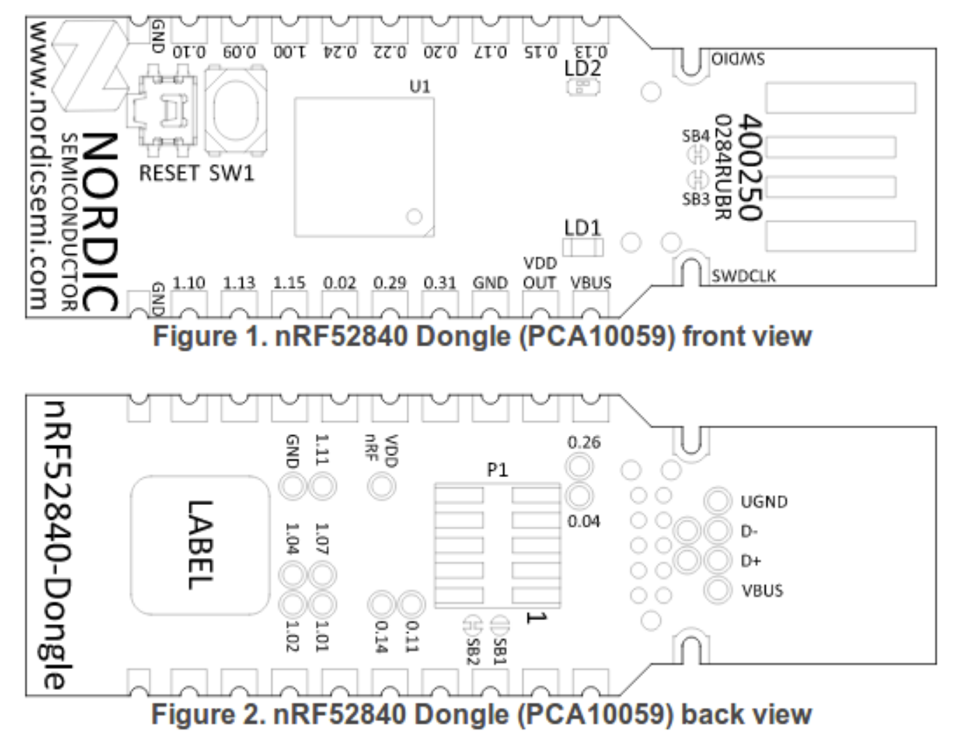
nrf52840 board pinout:
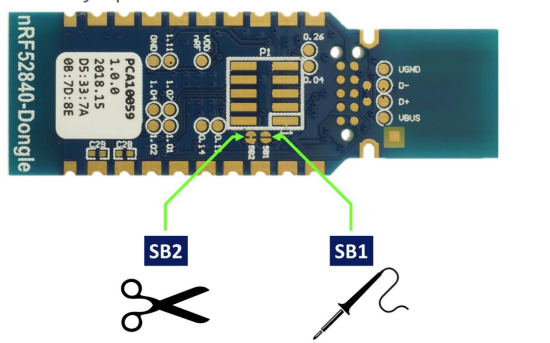
You MUST cut the SB2 and solder the SB1 pads on the bottom of the board:
3 - Build your enclosure - 3D print the enclosure and assembly.
3D print the STL files (can be printed in PLA and at 0.2mm layer height) All files are located in the stl directory
4 -Assembly:
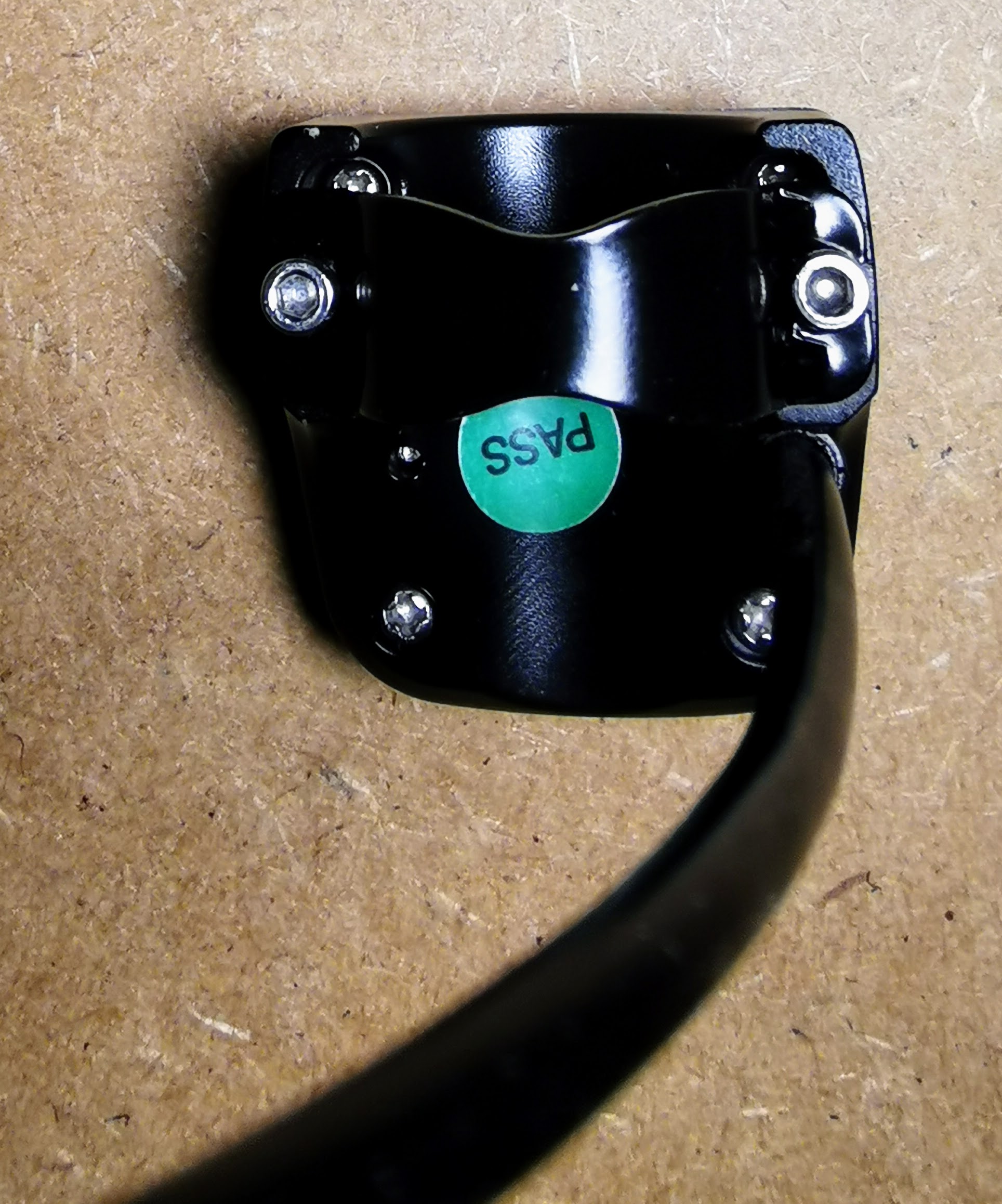
disassemble the wired remote by unscrewing the assembly from the bottom
![] (ebike_wireless_remote-05.jpg)
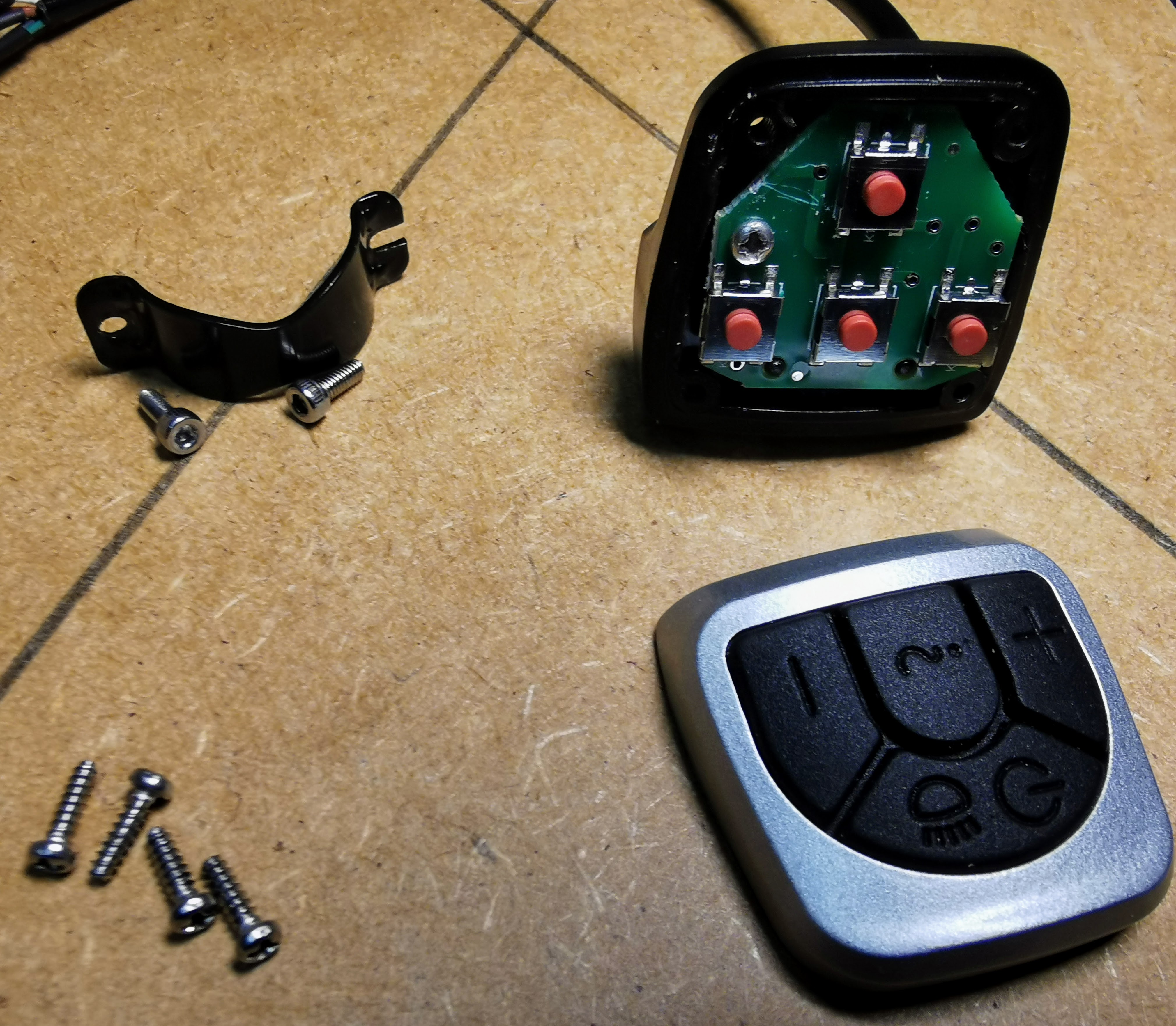
Save all the screws - you will need them later!
Remove the keypad from the VLCD5 as follows:
Gather the parts needed for the assembly:
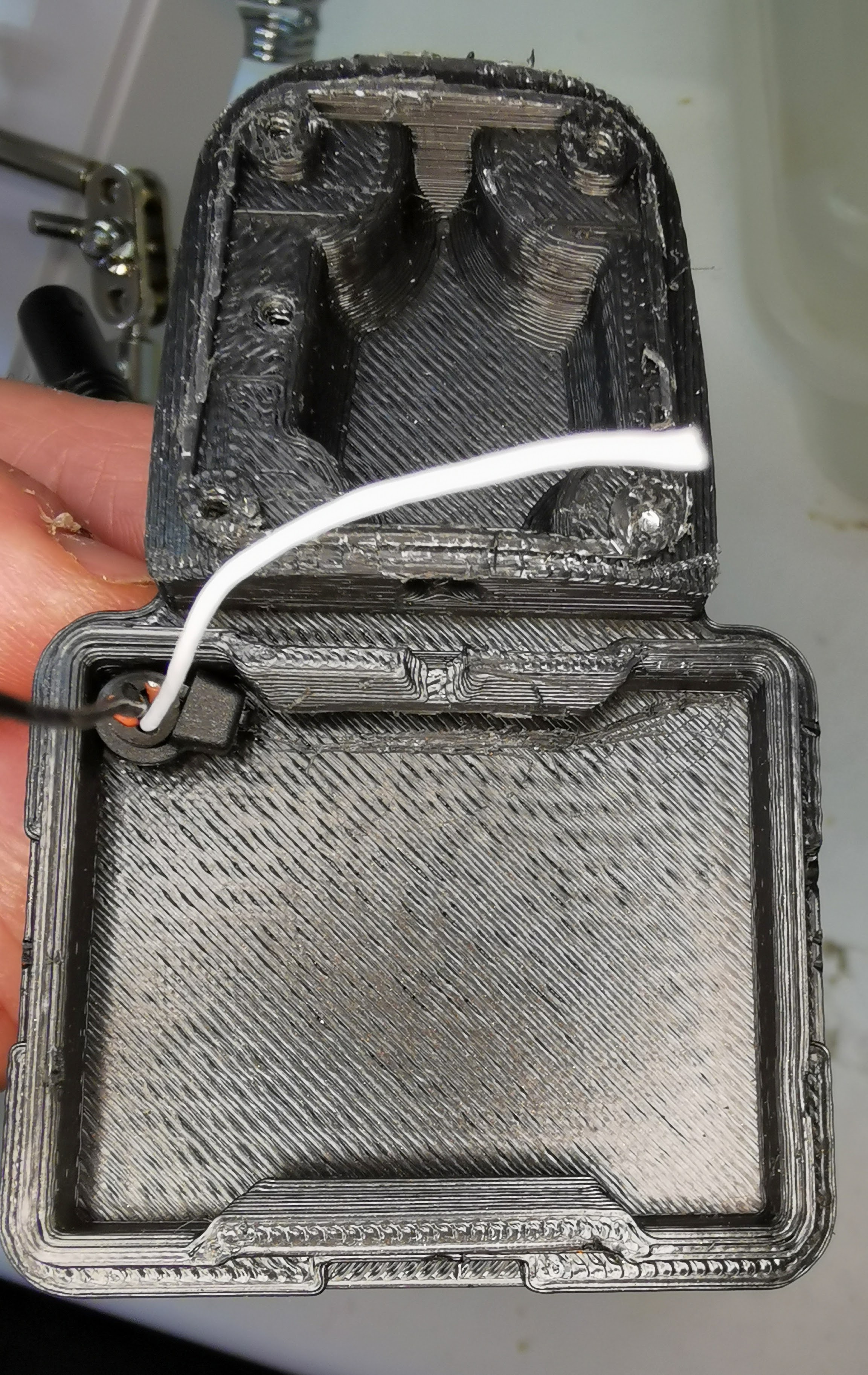
Push the brake wire throught the lower assembly and secure the wire with a small zip tie.
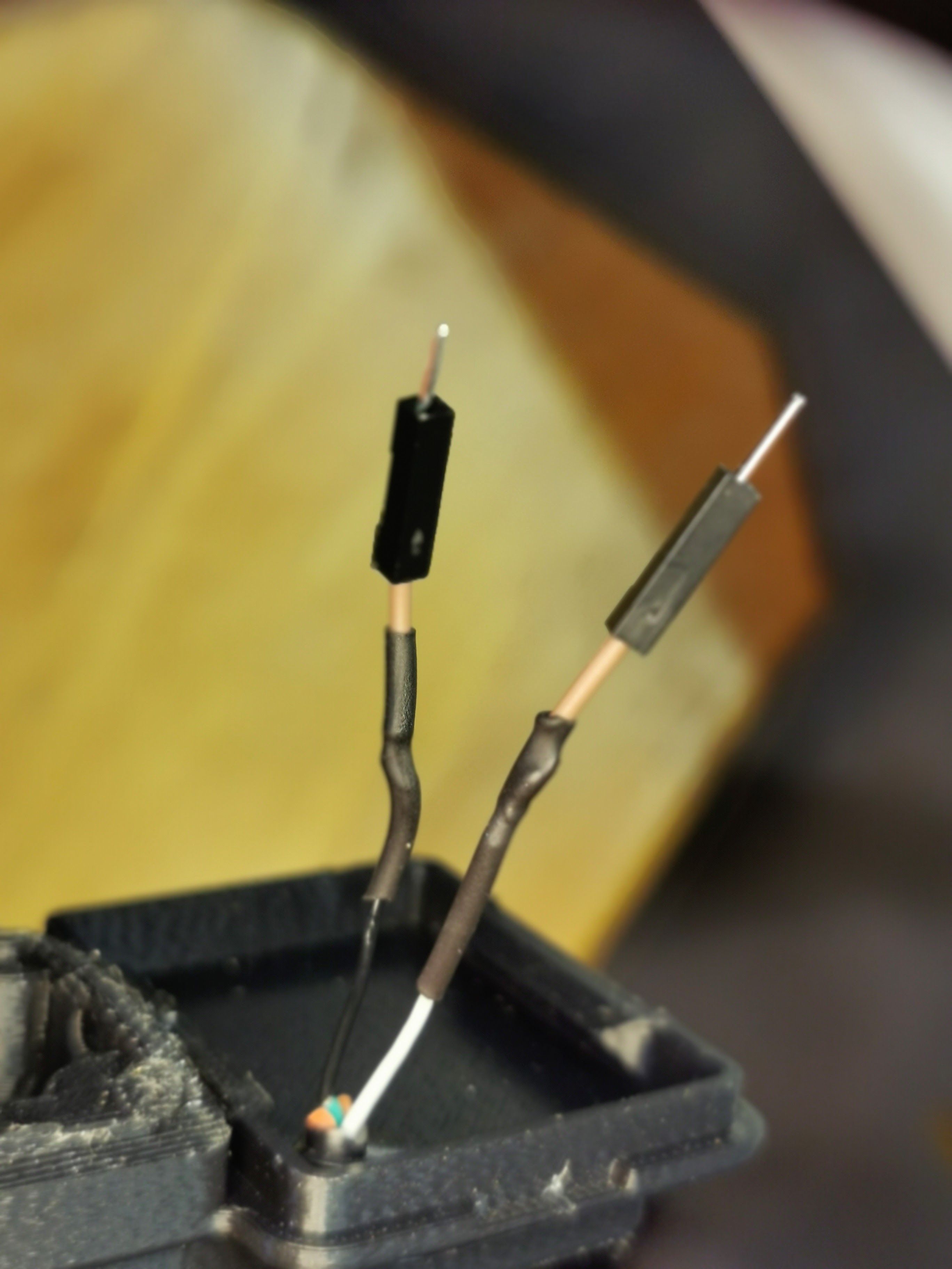
Solder a breadboard jumper cable to the end of the brake wires to allow for removable connections to the nrf52840 board:
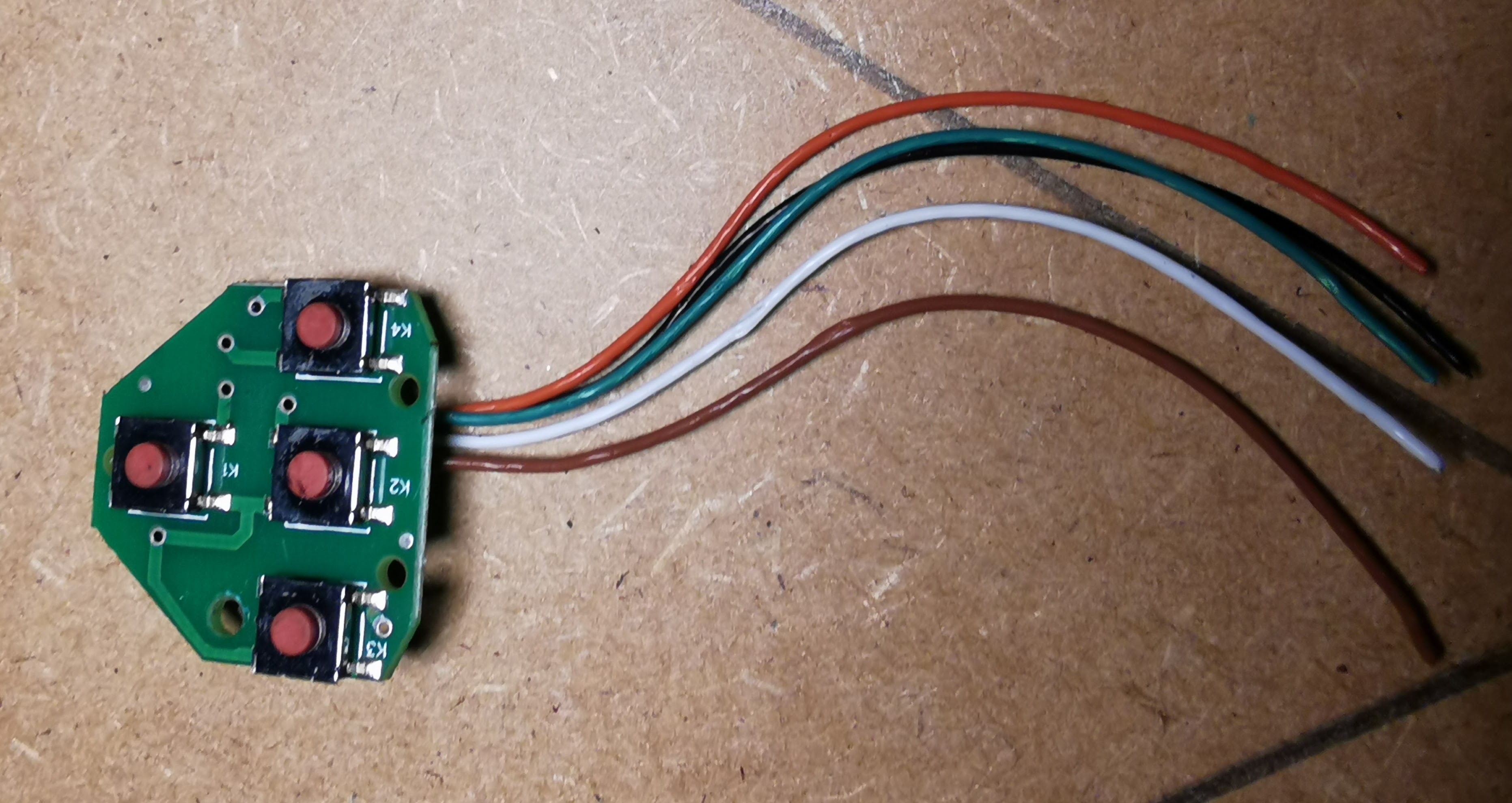
Solder all connections to the nrf52840 board:
Snap the top remote cover on the bottom case:
Screw in the button keypad:
Using the four screws from the original vlcd5 remote, screw in the button cover:
Insert the tie wraps thtough the bottom case:
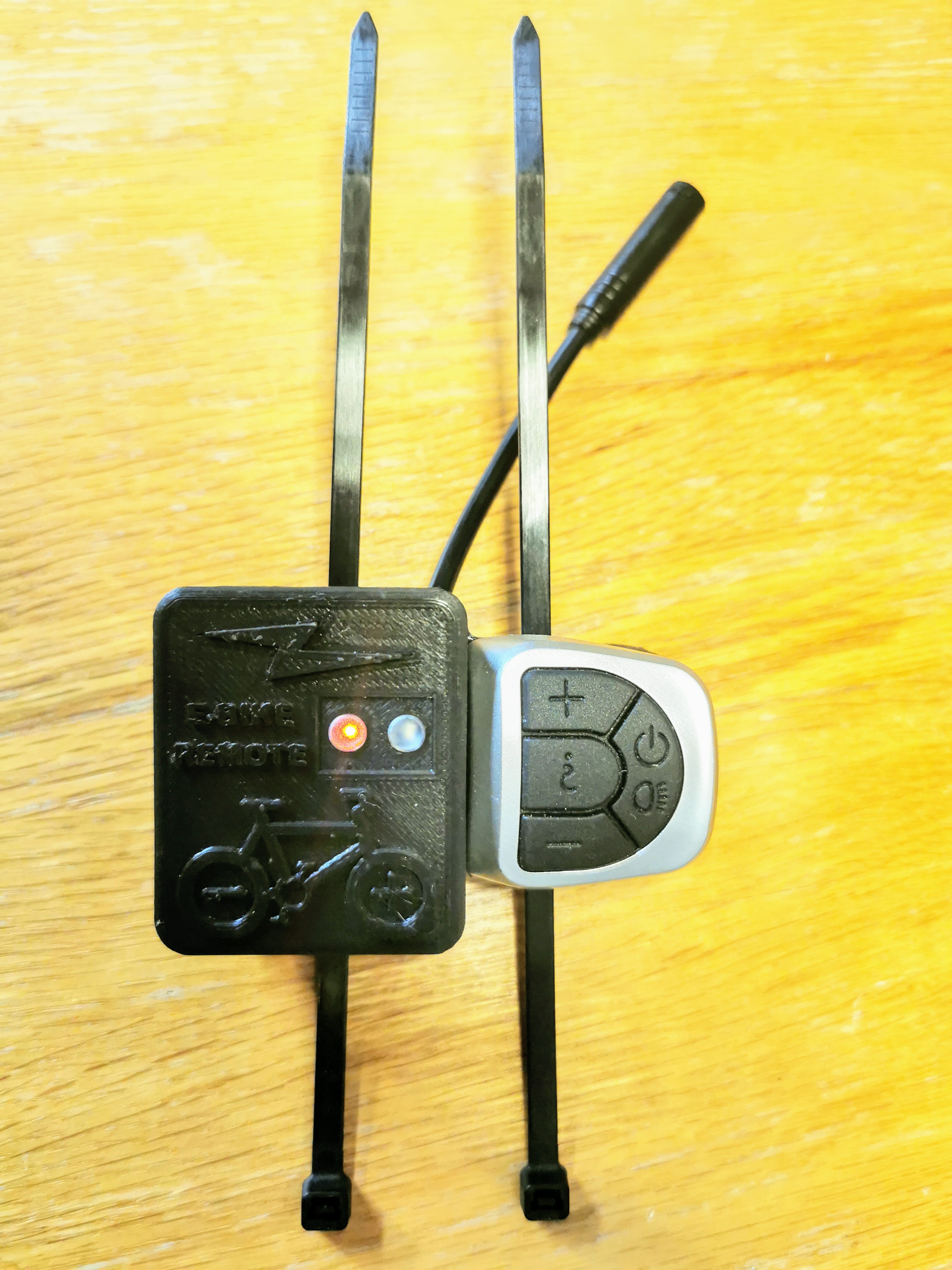
The final result mounted to the handlebar:<br)>
4 Flash firmware on the nrf52840 board using the wired connections - see the page: How to Flash the Wireless Remote and Motor Controller Firmware
5- Test - Make sure the TSDZ2 wireless board if off. Power up the remote board and the firmware will blink the LED (LD2) with red color attempting to connect to the TSDZ2 wireless controller.
Yet another possible re-design of the 3d enclosure
As a final note, I have been considering another redesign which would seperate the VLCD5 remote and the wireless electronics box.
This would have the advantage of reducing handlebar space and simplifying assembly.
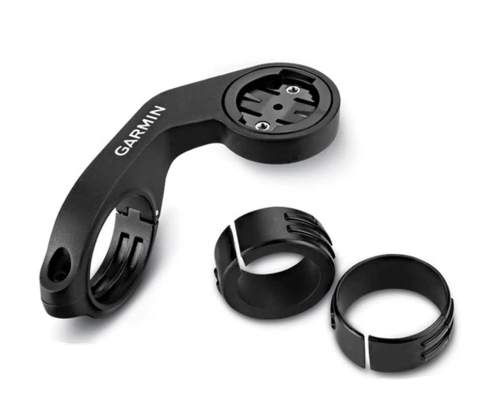
In this approach, the original VLCD5 remote would be mounted as usual, and the wire from this remote as well as the brake wires would be fed into a box containing the nrrf52840 and battery. This box would then be mounted to a garmin forward mount system like this:
Please comment on the forum if you would like to see this implemented.